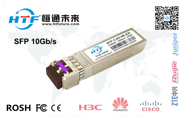
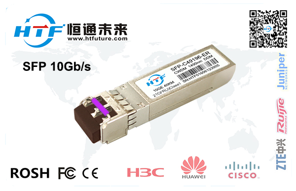
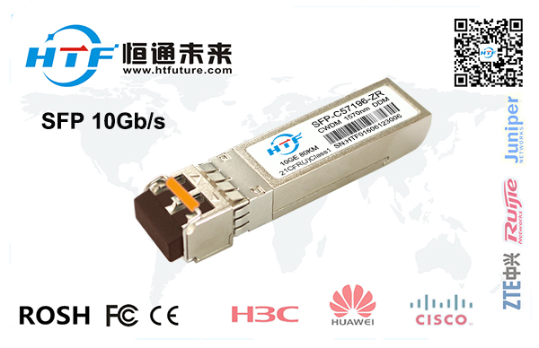
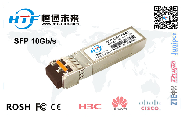
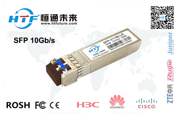
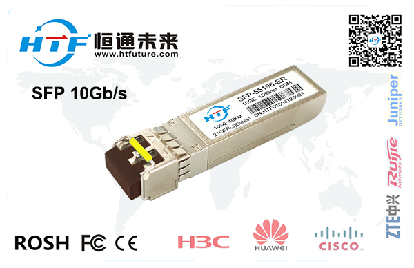
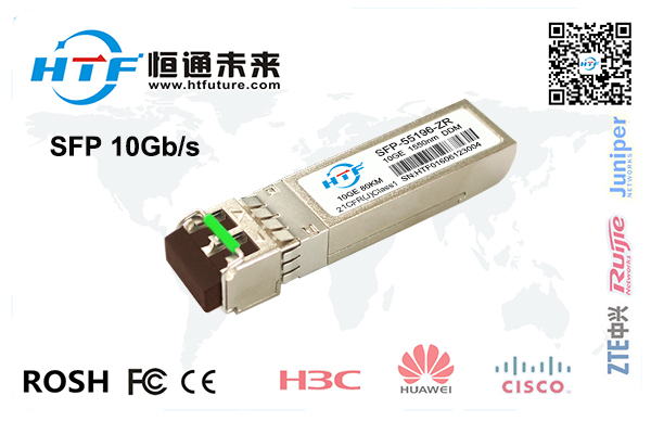
10Gb/s SFP+
10km Transceiver
Product
Features
l
Up to 11.1Gbps Data Links
l
Up to 10km transmission on SMF
l
Power dissipation < 1.5W
l
Uncooled CWDM DFB Laser and PIN receiver
l
Metal enclosure, for lower EMI
l
2-wire interface with integrated Digital Diagnostic monitoring
l
Hot-pluggable SFP+ footprint
l
Specifications compliant with SFF 8472
l
Compliant with SFP+ MSA with LC connector
l
Single 3.3V power supply
l
Case operating temperature range:0°C to 70°C
Applications
l
10GBASE-LR/LW 10G Ethernet
Standard
l
Compliant to 802.3ae 10GBASE-LR/LW
l
Compliant to SFF-8431
l
RoHS Compliant.
Product
selection
HTFPPC-XX96-10BD
Wavelength
xx
Wavelength
xx
1270
nm
27
1370 nm
37
1290
nm
29
1390 nm
39
1310
nm
31
1410 nm
41
1330
nm
33
1430 nm
43
1350
nm
35
1450 nm
45
Absolute
Maximum Ratings
Parameter
Symbol
Min
Typ
Max
Unit
Note
Storage
Temperature
Ts
-40
-
85
oC
Storage
Ambient Humidity
HA
5
-
95
%
Operating
Relative Humidity
RH
-
-
85
%
Power
Supply Voltage
VCC
-0.3
-
4
V
Signal
Input Voltage
Vcc-0.3
-
Vcc+0.3
V
Recommended
Operating Conditions
Parameter
Symbol
Min
Typ
Max
Unit
Note
Case
Operating Temperature
Tcase
0
-
70
oC
Without air flow
Power
Supply Voltage
VCC
3.14
3.3
3.47
V
Power
Supply Current
ICC
-
350
mA
Data
Rate
BR
10.3125
Gbps
Transmission
Distance
TD
-
10
km
Coupled
fiber
Single mode fiber
9/125um SMF
Optical
Characteristics
Parameter
Symbol
Min
Typ
Max
Unit
Note
Transmitter
Output
Opt. Pwr
POUT
-6
-1
dBm
1
Optical
Wavelength
λ
λ-6.5
λ+6.5
nm
2
Spectral
Width (-20dB)
σ
1
nm
Optical
Extinction Ratio
ER
3.5
dB
Transmitter
and Dispersion Penalty
TDP
3.2
dB
Side
mode Suppression ratio
SMSR
30
dB
RIN
RIN
-128
dB/Hz
Output
Eye Mask
Compliant with IEEE
802.3ae
Receiver
Receiver
Sensitivity
Psen
-14.4
dBm
3
Input
Saturation Power (Overload)
PSAT
0.5
dBm
Input
Optical Wavelength
λIN
1270
1610
nm
LOS
-Assert Power
PA
-17
dBm
LOS
-Deassert Power
PD
-30
dBm
LOS
-Hysteresis
PHys
0.5
dB
Notes:
1.
Class 1 Laser Safety per FDA/CDRH and IEC-825-1
regulations.
2.
λ”is:1270,1290,1310,1330,1350,1370,1390,1410,1430,1450,
please the “product selection” .
3.
Measured with a PRBS 231-1 test pattern,
@10.325Gb/s, BER<10-12 .
Electrical Characteristics
Parameter
Symbol
Min
Typ
Max
Unit
Note
Supply
Voltage
Vcc
3.14
3.3
3.46
V
Supply
Current
Icc
350
mA
Transmitter
Input
differential impedance
Rin
100
Ω
1
Differential
data input swing
Vin,pp
180
1200
mV
Transmit
Disable Voltage
VD
Vcc–1.3
Vcc
V
Transmit
Enable Voltage
VEN
Vee
Vee+ 0.8
V
2
Transmit
Disable Assert Time
10
us
Receiver
Differential
data output swing
Vout,pp
300
850
mV
3
Data
output rise time
tr
30
ps
4
Data
output fall time
tf
30
ps
4
LOS
Fault
VLOS fault
Vcc–1.3
VccHOST
V
5
LOS
Normal
VLOS norm
Vee
Vee+0.8
V
5
Power
Supply Rejection
PSR
100
mVpp
6
Notes:
1.
Connected directly to TX data input pins. AC coupled
thereafter.
2.
Or open circuit.
3.
Input 100 ohms differential termination.
4.
These are unfiltered 20-80% values
5.
Loss Of Signal is LVTTL. Logic 0 indicates normal
operation; logic 1 indicates no signal detected.
6.
Receiver sensitivity is compliant with power supply
sinusoidal modulation of 20 Hz to 1.5 MHz up to specified value applied through
the recommended power supply filtering network.
Pin
DeSCRJPTions
Pin
Symbol
Name/DeSCRJPTion
Note
1
VEET
Transmitter
Ground (Common with Receiver Ground)
1
2
TFAULT
Transmitter Fault.
2
3
TDIS
Transmitter Disable.
Laser output disabled on high or open.
3
4
SDA
2-wire Serial
Interface Data Line
4
5
SCL
2-wire Serial
Interface Clock Line
4
6
MOD_ABS
Module Absent.
Grounded within the module
4
7
RS0
Rate Select 0
5
8
LOS
Loss of Signal
indication. Logic 0 indicates normal
operation.
6
9
RS1
No connection
required
1
10
VEER
Receiver
Ground (Common with Transmitter
Ground)
1
11
VEER
Receiver
Ground (Common with Transmitter
Ground)
1
12
RD-
Receiver Inverted
DATA out. AC Coupled
13
RD+
Receiver Non-inverted
DATA out. AC Coupled
14
VEER
Receiver
Ground (Common with Transmitter
Ground)
1
15
VCCR
Receiver Power
Supply
16
VCCT
Transmitter Power
Supply
17
VEET
Transmitter
Ground (Common with Receiver Ground)
1
18
TD+
Transmitter
Non-Inverted DATA in. AC Coupled.
19
TD-
Transmitter
Inverted DATA in. AC Coupled.
20
VEET
Transmitter
Ground (Common with Receiver Ground)
1
05
09
2020
10KM彩光模块 10G彩光光模块 110KM彩光光模块 20KM彩光模块
来源:[深圳恒通未来科技有限公司]
联系人:胡先生
手机:18928411596
电话:0755-23777185(805)
传真:0755-23777185(808)
QQ:877340738
Email:877340738@qq.com
地址:广东省深圳市深圳市深圳市龙华新区大浪展润商务大厦10楼
品牌:HTF/恒通未来
价格:100.00
元/只
供应地:广东省深圳市
产品型号:10Gb/s SFP+ 10km
